Where I illustrate developing multitasking code for the ATmega328P using a new Standard C framework.
Sources#
- A Multitasking Kernal in One Line of code Simplistic, yet powerful approach to multitasking. examples/oneline
- AVR Scheduler Nicely documented Round Robin Scheduler. examples/RR_Scheduler
- Preemptive Multitasking for the AVR Simplified OS which provides multitasking. examples/RIOS
- Writing a Preemptive Task Scheduler for AVR
- avr-libc Standard AVR C Library
- Github: Programming the Arduino Uno in C
- Multi-tasking the Arduino - Part 1
Introduction#
The value of using multitasking on an embedded microcontroller, is that it allows you to do “multiple things at once”, hence the term multitasking. It also allows you to separate specific tasks into functions. Then debug each function separately to ensure your board works as bug free as possible.
As this description states, there are three fundamental methods to multitask:
- Single, infinite loop
- Loop augmented by interrupt service routines (ISRs)
- A number of independent loops, augmented by ISRs
And while the third approach is more than likely the most, robust approach, it is much more complex to implement. The article goes on to introduce scheduling approaches as well. Ultimately, it provides a core code example (oneline) below then evolves that example to help you to begin to develop a multitasking solution.
There are three examples included in AVR_C to provide ideas as to how to multitask. I’ll be evolving oneline into a new example which will be incorporated into the Library, called multifunction. The goal of multifunction is to provide a framework for different functions to be performed in a specific amount of time with a minimal amount of code and a focus on speed.
oneline#
To begin writing multifunction, I started with oneline. It is interesting because it is very simple and easy to understand. The basis of the scheduler is this code:
    while (1)
    {
    for (uint8_t taskcount=0; taskcount < NTASKS; ++taskcount)
        {
            (*tasklist[taskcount])();
        }
    }
This code is a bit more than “one line of code” as promised in the headline and it appears the example on the page doesn’t work as it won’t compile. This code will compile as will the main.c file in the oneline example folder.
As the code is so simple, I spent time attempting to make it as fast as possible and as small as possible. The compiled code was 466 bytes and will light three LED’s (each in a separate task) in succession, each at 200kHz. The basis of the code is cycling through an array which points to the addresses of the three tasks.
This is the basis of all task-control-blocks, in this case, there is only one parameter, the task address. As we get to more complex examples, we will add more parameters to account for execution priority and time slice allocation. Ultimately, the most complex and robust examples will also add save all of the registers and any variables specific to the task.
This approach is great for a situation where precise, timed execution isn’t important, speed is important and each task can finish prior to the next task being executed (non-preemptive).
Viewing the tasks#
Once I began to work with multitasking code, I needed to have a deeper understanding as to how the code was functioning. For example, I created a very simple 3 task application using the scheduler above. All the tasks were identical, except each one toggled a different LED. The function code was:
void zero (void) {
    /* writing a 1 to the port input register will toggle pin */
    PIND |= _BV(LED0);
    return;
}
And when I ran the code, the LED’s were all seemingly on all the time, however when I measured the frequency on an LED, it was 200kHz and a duty cycle of 35%. Which means the three tasks were consuming about 5 microseconds and each task took about 1/3 (35%) of the time period. When I measured this on a scope, I saw:
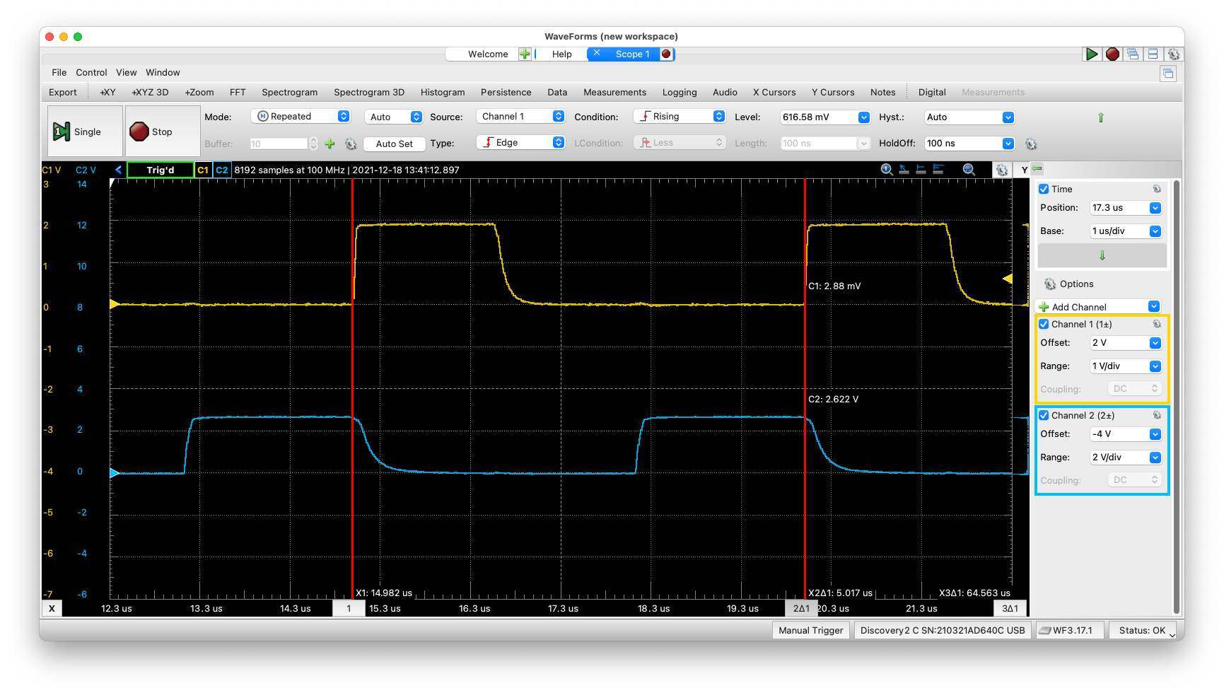
Oscilloscope view of 2 of 3 tasks
Large Version to see detail The orange trace is task 0 and the blue trace is task 2, the flat part of the wave in the middle of the two pulses is the unseen task 1 going high. Each task takes about 1.7 microseconds and the total time is 5 microseconds. All of this makes sense.
I then placed a delay (5 milliseconds) into one of the three tasks expecting to see that specific LED begin to blink, while the others would be “on”. Instead I got almost a solid “on” on the led with a delay and a steady off with the other two. When I attempted to measure the signals, I saw a very narrow high-to-low on the delayed task and a very narrow low-to-high on the other two. Essentially, it was outside of my scope’s ability to register the two waves.
So I took another approach, I added a delay to two functions and left one function alone. With this I got the following:
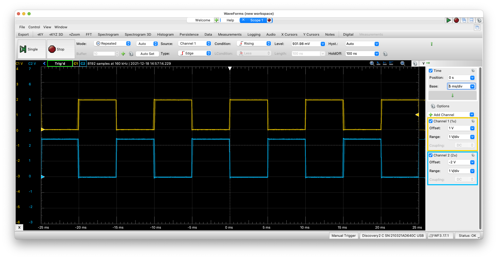
Oscilloscope view of 2 of 3 tasks, both have a delay of 5 ms
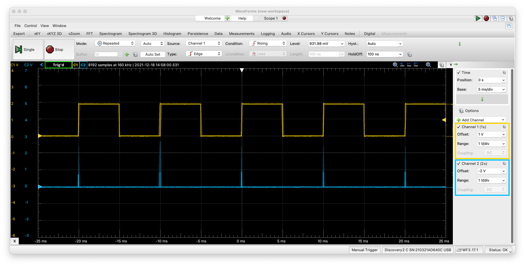
Oscilloscope view of 2 of 3 tasks, only one has a delay of 5 ms
Large Version to see detail
The two views make sense, given that we already know that a function without a delay takes about 1.5 microseconds and the delayed function takes about 5 milliseconds, about (3000 times longer) hence you can’t see the spike.
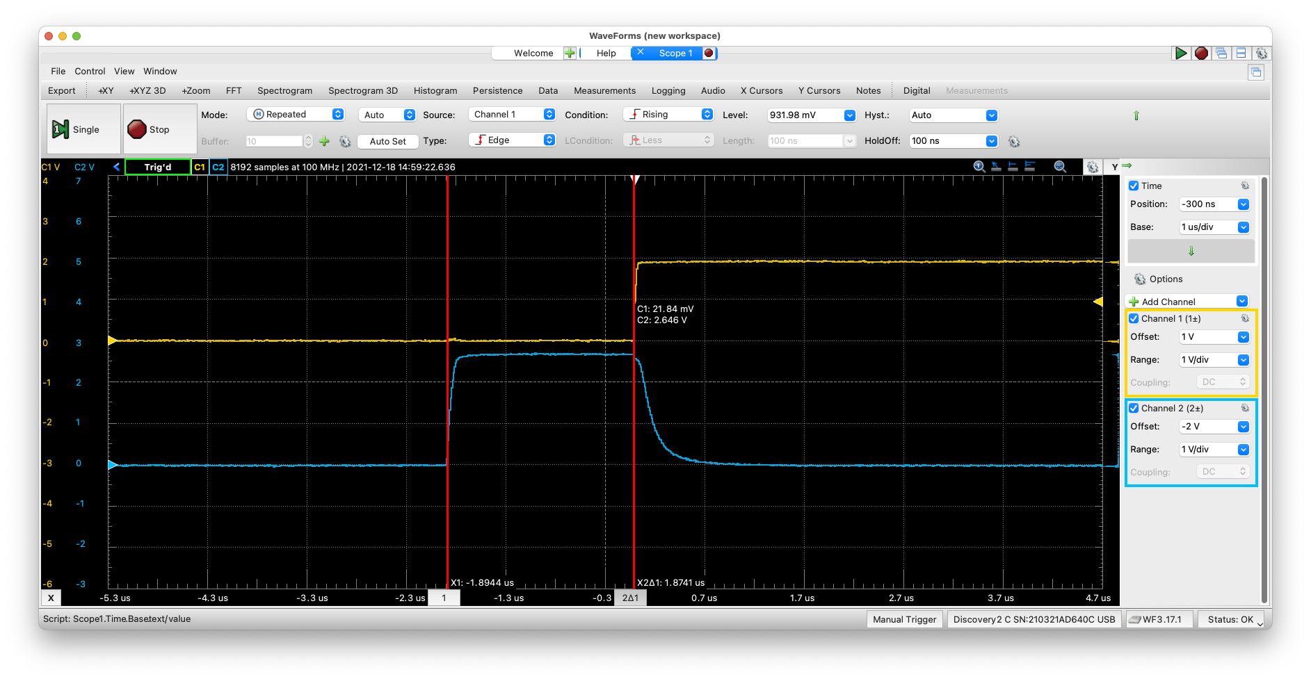
Detailed view of 1 of 3 tasks, the one without the 5ms
Large Version to see detail The view above shows the width of the spike as 1.87 microseconds, so the function is working, it is has a much smaller execution time than the other two.
One last analysis would be does the time of the notch make sense? We know that a clock period for a 16Mhz clock would be 62.5nanoseconds. And from our main.lst file (using make dissamble), the assembly code looks like this:
void two (void) {
    /* toggle led on and off */
    PIND |= _BV(LED2);
  ae:   89 b1           in  r24, 0x09   ; 9
  b0:   80 64           ori r24, 0x40   ; 64
  b2:   89 b9           out 0x09, r24   ; 9
    return;
}
  b4:   08 95           ret
Which is 3 instructions or 3 * 62.5 ~= 1.87 microseconds…what I am unable to explain is why the signal goes low again, as the writing to PIND, merely toggles the pin. It doesn’t turn it on then turn it off.
For now, I’ll use it from a macro sense, meaning the timing will be longer and in the millisecond range. The wave from makes sense when viewed from the perspective of having a 5 millisecond delay, as the wave is on for 5ms then off for 5ms.
multifunction#
To take the multitasking to the extreme, I created a new example called multifunction using the oneline as the basis. In this case, instead of 3 functions, I created 10 functions to see if this code would scale. It did! And the parameters changed with the number of functions, for example, the duty cycle changed from approximately 35% with three tasks to about 10% with 10 tasks. The frequency of each task went from 200kHz to 67kHz.
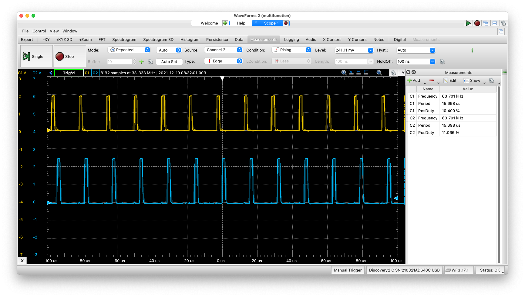
Oscilloscope view of 2 of 10 tasks, running at full speed
multi_Ard#
For multifunction, I used bit level commands like _BV to change the level of the pin. Using these commands is extremely efficient, however they don’t translate well when attempting to refactor the code. Each _BV command needs to have a specific port and pin, calculated at compile time, in order to be successful.
In this version of the code, I changed to the Arduino method of manipulating the pins. I use pinMode() to make the pins and output pin and digitalWrite() to set the pin level. The execution of the code is identical to multifunction, however the code runs much slower due to the overhead consumed by easing the programming interface. The image below shows the 67kHz frequency of a pin toggling is now down to 17kHz.
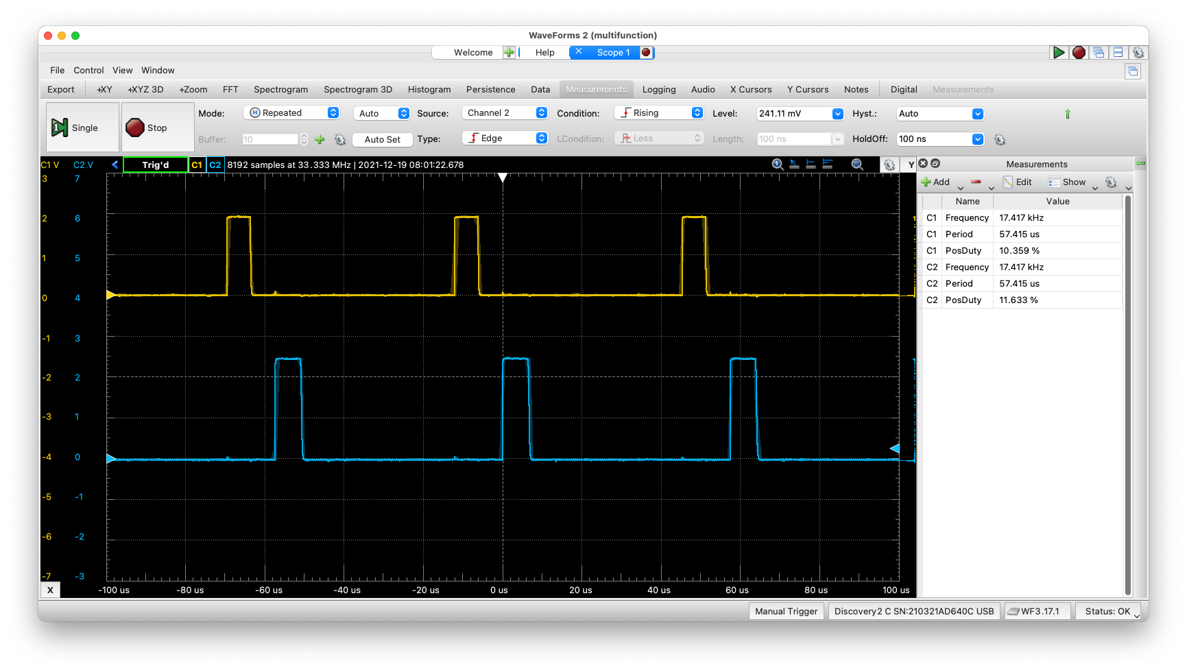
Oscilloscope view of 2 of 10 tasks, using the Standard C framework code
multi_array#
Clearly, maintaining ten independent functions for very similar activities is not efficient from a programming perspective. And moving to the Arduino-type framework, allows us to replace 10 independent functions with one function, however we pass it an index to reference for the pin location. This reduces the number of lines of code from 118 to 35, the program size from 830 bytes to 640 bytes and the RAM required from 22 bytes to 2 bytes. We pick up a slight increase in speed from 17kHz to 19kHz.
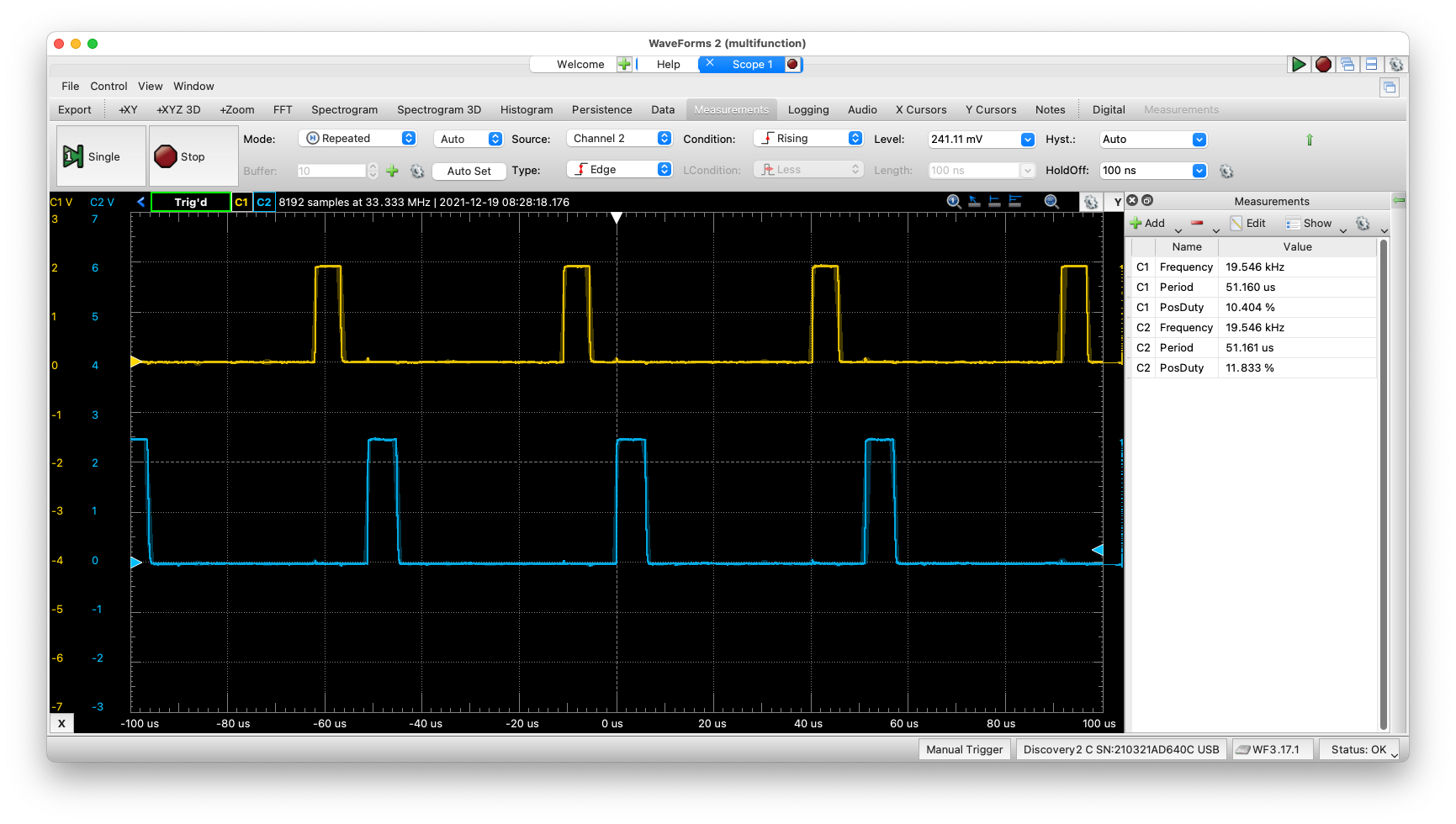
Oscilloscope view of 2 of 10 tasks, using the Standard C framework code and an array instead of 10 functions
Large Version to see detail This is probably the least interesting and effective version of all the programs as it excepts the execution to be identical for each task.
multi_struct#
Which brings us to a much more interesting approach. We continue to use the one function execution approach, however, we take a page from Adafruit’s multitasking example. In their example, they use classes from C++. The C language doesn’t have an object-oriented element such as a class, however, they have something which will work as well, a struct.
In our case we use a struct, to create a single-index, multiple type array which can contain a much richer amount of information as to what the function needs to accomplish. We add to the struct, the same update code which Adafruit uses, called update. If you review the approach, I took in multifunction, it is very similar. Except in multifunction, the structure was only used for the function address, in this case it is used for all of the parameters. It was be very easy to add back the address of the function so that multiple types of functions could be use, one function for an LED, another function for a speaker, etc.
typedef struct task {
   uint8_t pin;             // Uno pin number
   uint8_t state;           // Is led on or off
   uint16_t on;             // Time led is on
   uint16_t off;            // Time led is off
   uint16_t elapsed;        // Time elapsed sinced last in loop
} task;

task tasks[NTASKS];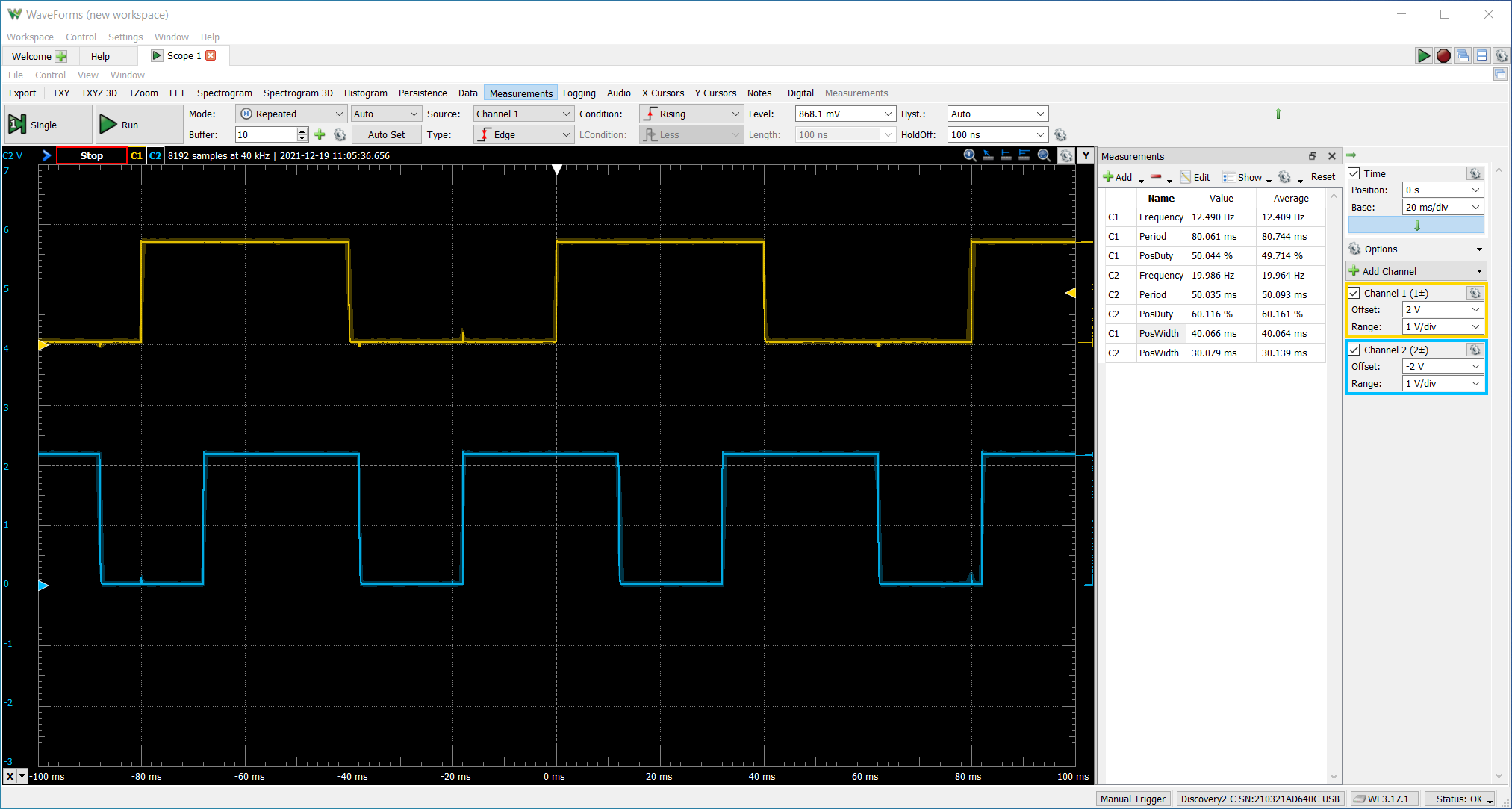
Oscilloscope view of 2 of 3 tasks, using a struct for control parameters
This version does use more code, 964 bytes of program memory and 26 bytes of RAM. That said, notice what it can do that no of the preceding examples could do. Overlap waveforms! Now we are able to specify an on-time and an off-time for each led. Those times are independent of the other LEDs, which you can see in the image above.
Update: Optimization#
After thinking about the speed of execution (in that it is extremely slow) when using the Arduino-like C command of digitalWrite(), I wanted to return to the approach I originally used in multifunction. In multifunction, I used bit setting commands to directly affect the pins instead of using digitalWrite(). When you compare multifunction to multi_Ard, where the execution of the two programs are identical, multifunction runs at 63kHz, while multi_Ard runs at 17kHz. This almost 4x in performance is worthwhile and important when multi-tasking.
With this in mind, I went back to multi_struct and updated the code to use bit manipulation instead of digitalWrite(). I was able to do this by adding two fields to the struct, port and bit. These are the two fields required when performing a bit_set or bit_clr command. The fields are determined at the same time as when performing the pinMode() action of setting the bits to OUTPUT. Note, as this is performed only once at the beginning of the program, there is little value in optimizing pinMode() out.
I can’t show a definitive increase in speed as the program wasn’t designed to show maximum performance using the milliseconds from millis(). I think a better approach is to re-examine sys_clock to create a faster version of millis(), which would enable higher performance. My last comment is the new version does use more RAM 35 bytes (from 26 bytes), however it reduces program storage to 874 bytes (from 964 bytes).