How to install the software then perform a hardware calibration.
The video assumes you have installed the Labrador application and wish to better understand how to do a calibration. It also shows how to solve a multimeter software bug.
Overall Process:#
- For all of the OS versions; Windows, Linux, macOS, go to the github releases page for the Espotek Labrador and download the appropriate image.
- Each OS has its own set of installation instructions, and are very similar to other installations for the same type of software.
- Once installed, calibrate and perform the simple test in this presentation to confirm its operating properly
Comments on Installations#
- Windows
- Typical install with multiple click-throughs
- Make sure you note where you installed it
- Double-click the application to start the application
- Linux
- Use Appimage version to keep installation simple
- Two right-click operations to start the application
- macOS
- Drag download to Applications folder
- Right-click to Open
- Click on Open to start the application
Hints for next steps#
1. Calibrate the Oscilloscope#
To make it easier to connect both wires to USB shield:
- Insert jumper wires from both Oscilloscope sockets to an empty row on the breadboard
- Add another jumper wire to that row
- Use the single jumper wire to touch the USB shield
- Watch the screen to see the signal goes to zero before hitting Enter (or Return)
Simplified Labrador calibration
2. Calibrate the Power Supply#
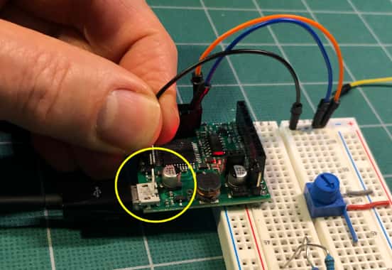
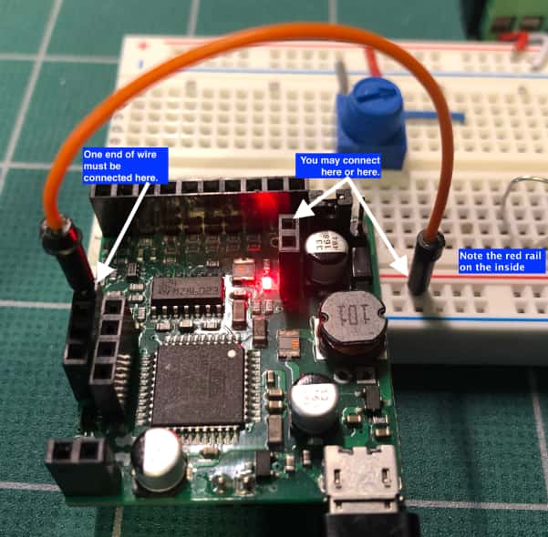
You may plug the Oscilloscope wire into the socket on the Labrador or on the breadboard. Be sure to check how the Labrador is plugged into the breadboard. The power pin (red +) needs to go into the positive rail on the breadboard. This means the Labrador needs to plug into the end that has the positive rail on the inside of the breadboard. (see image)
Illustrated Labrador PSU calibration
3. Test the Oscilloscope and Signal Generator#
Plug jumper wires from both Oscilloscope channels into the second row on the breadboard.
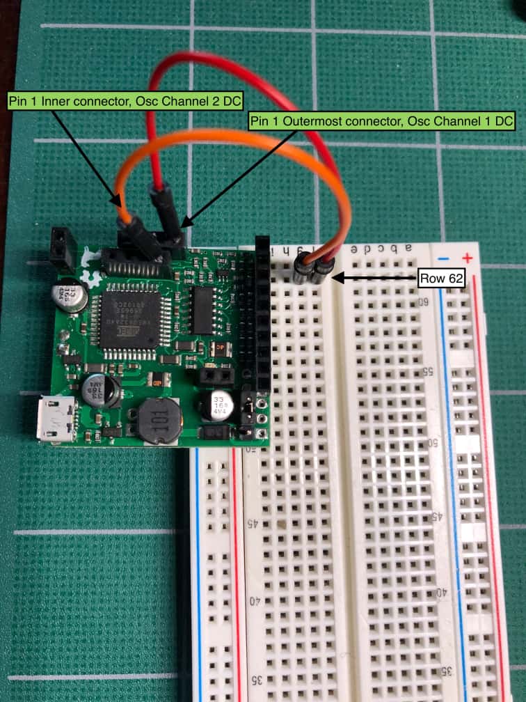
Labrador performing a closed loop test
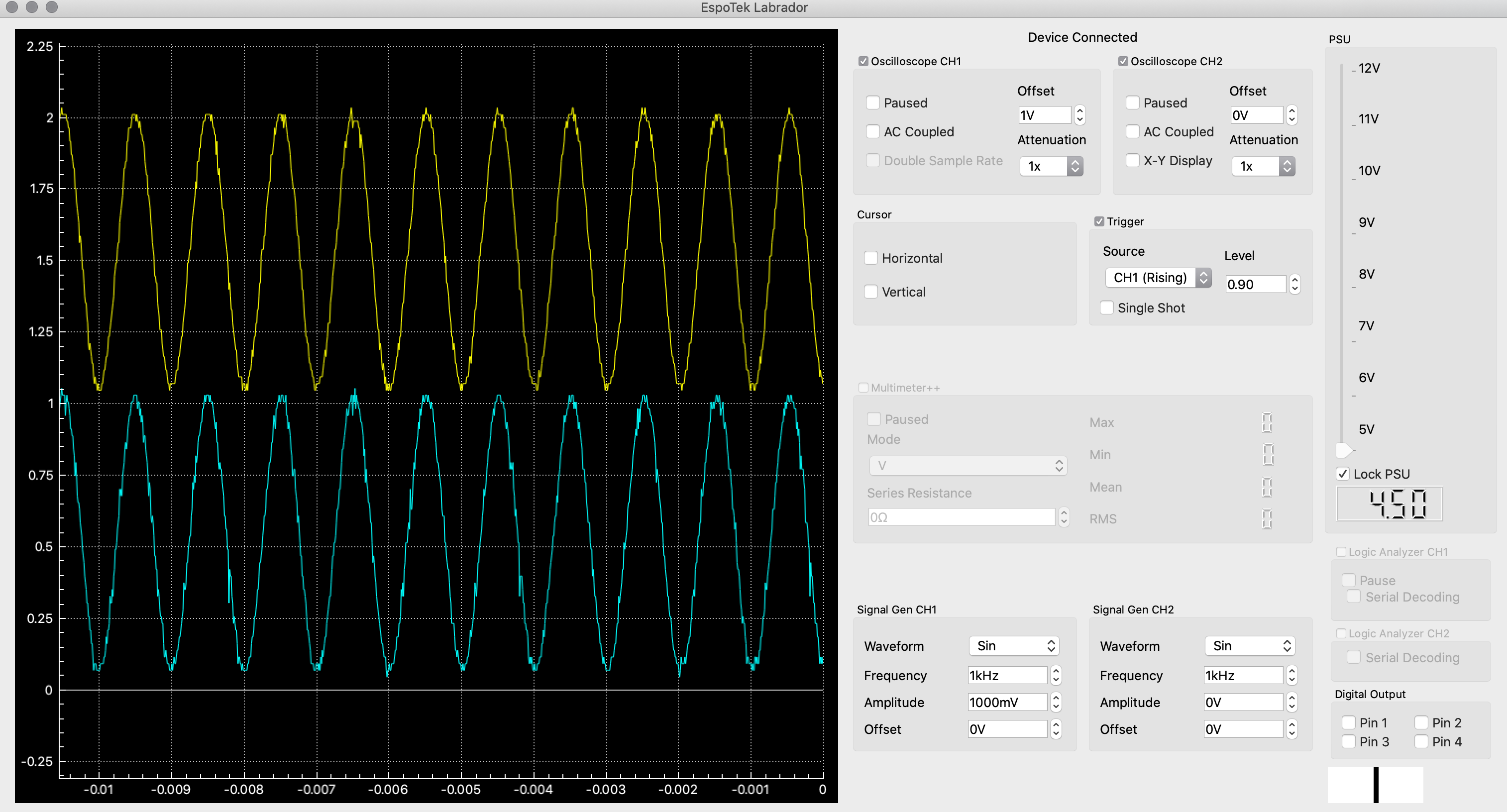
In the Labrador Application, in Signal Gen CH1:
- Waveform: Sin
- Frequency: 1kHz
- Amplitude: 1000mV
- Offset: 0V
To have both signals show on the scope, you will have to give one of the Oscilloscope channels an offset. In this image, we’ve given CH1 a 1V offset so it sits 1V above CH2.