Where I show some examples as to how to use Bloom and avr-gdb to debug code on the ATmega328P.
Sources#
- gdb Resources
- gdb Hints (from RP2040 effort)
- Bloom (replaces avarice)
- Microchip SNAP (replaces the Atmel Dragon)
Introduction#
In a previous entry, I discussed how to setup Bloom and gdb using an MPLAB Snap. Given the power of Bloom’s feature called Insight, I want to present some examples of how to use Insight to debug the AVR8 family of microcontrollers.
Exploring PWM using TC Registers#
A key aspect of Bloom is Insight, the ability to view all of the registers and memory on an AVR8 family microcontroller. It is an greatly enhanced version of program I’ve developed on this site, PinTest. PinTest provides an interactive method of testing each pin on a microcontroller board. I’ve written the program in C, MicroPython and Forth.
Insight is far better! It provides a graphical user interface of every register, not just the hardware pins. For example, this allows you to easily make changes to the Timer/Counter registers and see the PWM waveform change on an oscilloscope!
I’ll walk through a previous example of this entry where I set up TC0 to provide a PWM signal on pins 5 and 6. In a nutshell, the following registers need to be set to provide a 50% duty cycle, 975Hz signal on pin 6 (if you wish to understand more about how this code works, see the example linked above.):
    // TCCR0A [ COM0A1 COM0A0 COM0B1 COM0B0 0 0 WGM21 WGM20 ] = 0b10110011
    TCCR0A = _BV(COM0A1) | _BV(COM0B1) | _BV(COM0B0) | _BV(WGM21) | _BV(WGM20);
    // TCCR0B [ FOC2A FOC2B 0 0 WGM22 CS22 CS21 CS20 ] = 0b00000011
    TCCR0B = _BV(CS21) | _BV(CS20);
    OCR0A = 63;
    // Set Port D pins 5 and 6 (Uno pins 5 and 6) to output
    DDRD |= _BV(DDD5) | _BV(DDD6);
Insight provides a search window and it is intelligent as to how it handles registers. For example, it understands that TCCR0A, TCCR0B and OCR0A are all part of Timer/Counter 0.
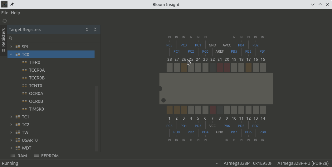
Timer/Counter 0 Registers in Bloom Insight
Large Version to see detail
Double-clicking on any one of the registers will open it for editing in a new window. In the next window we open TCCR0A, you may set the bits specifically by clicking on the boxes, I did so to set “10110011” and clicked Write Value to save the register. The time written is noted on the left-hand side.
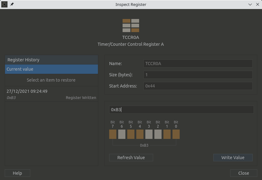
Setting the bits in TCCR0A
Large Version to see detail
We do the same for TCCR0B, set the bits to 0b00000011. In the image, we haven’t saved them yet.
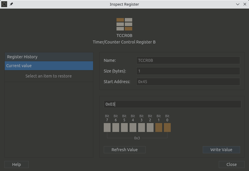
Setting the bits in TCCR0B
Large Version to see detail
We write hex 7f or 127 into the OCRA register to get a 50% duty cycle. In this case, I entered the hex value in the box above the pins.
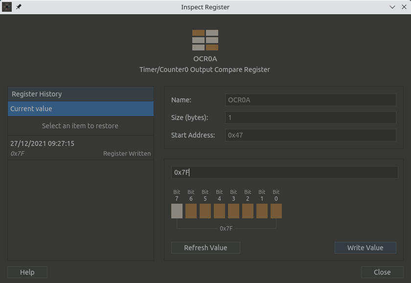
Write a value into the OCR0A register
Large Version to see detail
And finally, we need to make sure that pins 5 and 6 are OUTPUT, so we write a 1 to the respective pins in the DDRD register.
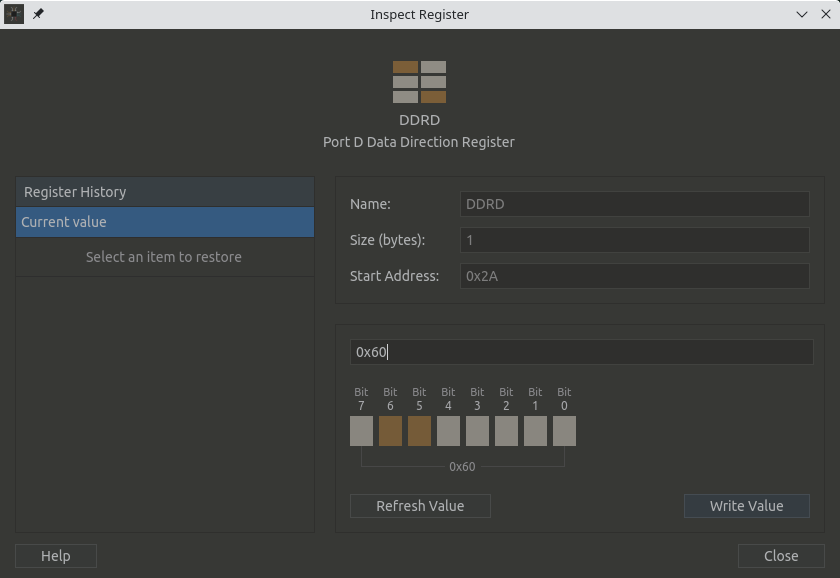
Timer/Counter 0 Registers in Bloom Insight
Large Version to see detail
We are using the Digilent Analog Discovery 2 to view the waveform and it looks perfect!
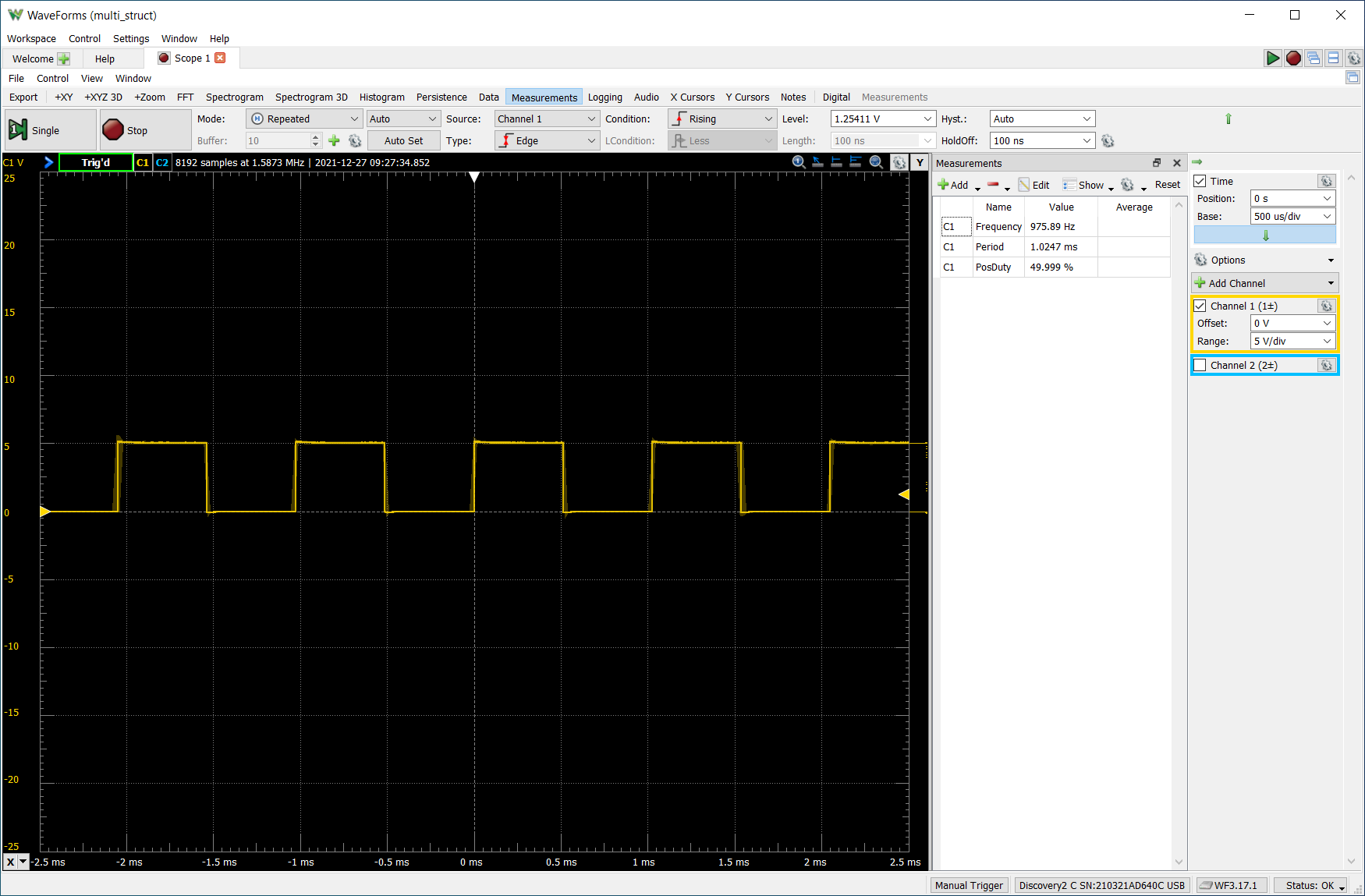
Waveform from pin 6 of the Arduino Uno
Exploring EEPROM for Printing#
Exploring RAM for Understanding Memory Regions#
[To see how to setup regions go here]
This example is about wrong assumptions. (I encourage you to read Guide to Faster, Less Frustrating Debugging as to Norm Matloff’s comments as to “beliefs” and debugging.) In the program multi_struct, while setting up the struct for tracking the tasks, I had defined the Port pointer to be uint8_t, forgetting that a pointer will be to memory so it will actually consume 2 bytes. Without getting into the specifics as to how PORT pointers are defined in avr-gcc (the value will need to be defined as uint8_t, the address or pointer will be uint16_t), I want to show how I realized I needed to think of the port pointer to be 2 bytes.
This is how the struct was defined:
typedef struct task {
uint8_t pin; // Uno pin
volatile uint8_t *port; // Port for Uno pin
uint8_t bit; // Bit in Port for pin
uint8_t state; // Is led on or off
uint16_t on; // Time led is on
uint16_t off; // Time led is off
uint16_t elapsed; // Time elapsed sinced last in loop
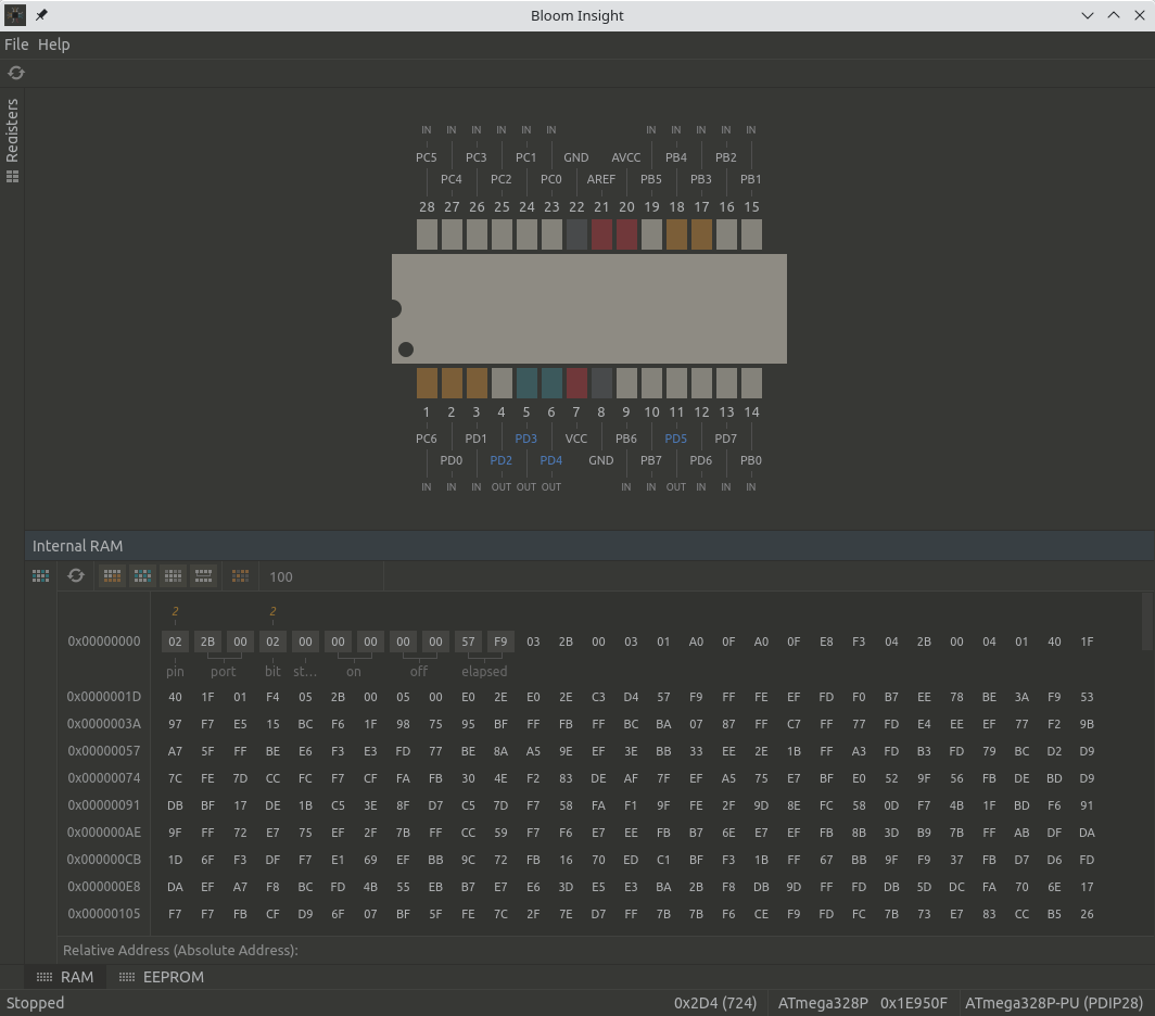
} task;As I was setting up memory allocation in Bloom’s Insight window, I made the mistake as I saw the uint8_t for the Port pointer and allocated it an 1 byte width in Insight. Which lead me to believe the value for state was 2, when it can only be 0 or 1. And the value for elapsed was BB00. To see this, look at the annotated line in the image below, showing the names of the struct elements and the values above them.
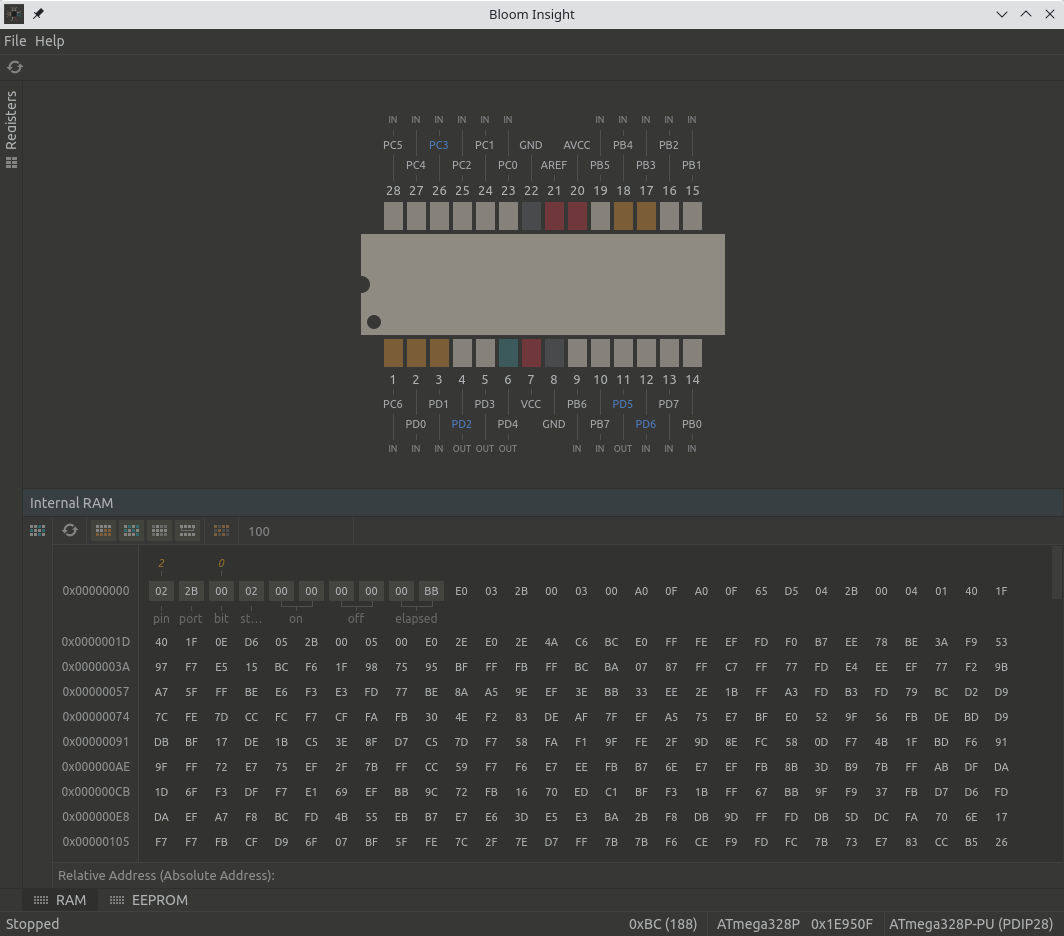
Improper setup of memory in Insight, look at annotated line
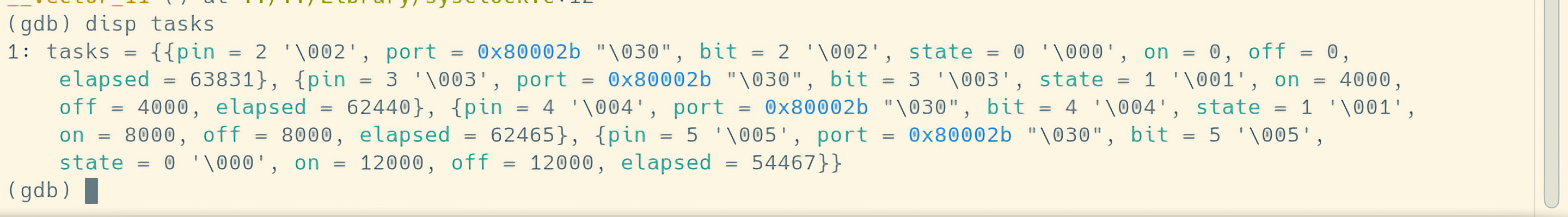
When I reviewed the same data via gdb, I realized my error. As the Port pointer was 2 bytes and state was 0 and elapsed was a decimal 57531 or E0BB. To see this, look at the second line where you see “pin=2 ‘\002’, port = …”
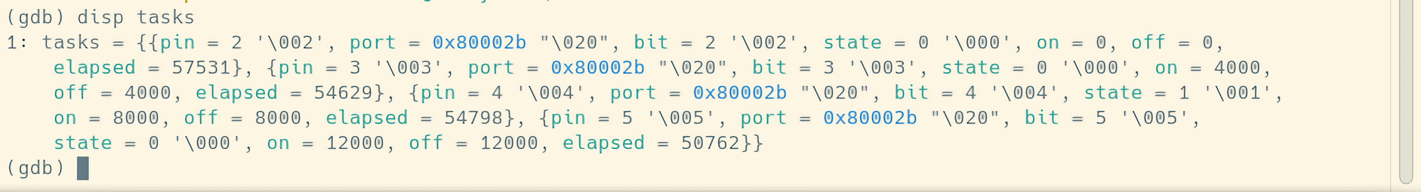
Same data in gdb, with proper values
I then realloacated the memory in Insight to be the correct view. The pointer is 2 bytes, state is 0 and elapsed is correct as well for hex F957 equals decimal 63831. (The values changed as I allowed another cycle of execution.)
Correct setup of memory in Insight, look at annotated line
Large Version to see detail
Confirmed data in gdb