Where I take the next step in developing code in C for the ATmega328. This time, I review the PWM functionality of the ATmega328.
Sources#
- Microchip AVR ATmega328 Go to this page for the datasheet, you will need it.
- Definitive UNO pinout, see below
- avr-libc Standard AVR C Library
- Secrets of Arduino PWM Great tutorial as to how to write code for PWM on the ATmega328
- DIYODE: PWM Classroom Great educational article on PWM and DC Motors
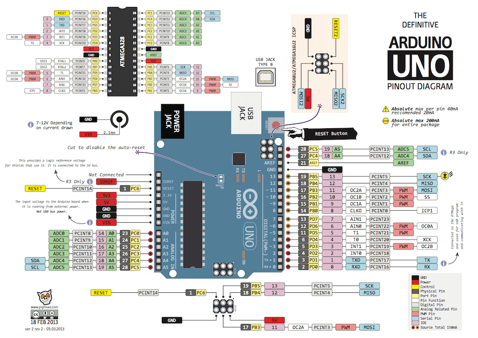
Arduino Uno Pinout
Introduction#
Pulse-width modulation (PWM) is a useful technique for controlling DC motor speeds, LED intensity and creating analog waveforms. The idea is to modulate (or change) the width of a digital signal (a pulse) to deliver a varying amount of voltage. The change is called the “duty cycle”, it will range from 0-100%, and the high the number, the greater the voltage delivered. PWM is valuable as it allows you to use less power to keep motors running or make LEDs bright. If the concept remains foreign to you, I recommend you read the noted sources above before going forward.
The Arduino uses PWM for its analogWrite(pin, duty cycle) function. It will deliver the same frequency 490Hz on one of 6 pins with the stated duty cycle. The 6 pins (3,5,6,9,10,11) have a “~” next to its pin number on the Uno board. The analogWrite function provides flexibility (any one of the 6 pins) at a cost of fixed frequency (490Hz) and code size (5 times the size of standard C code size for a similar signal on a fixed pin).
As an engineer, I have issues with two aspects of analogWrite. First, the code size is significant, almost 1K bytes of program space to deliver a PWM signal to any one of the 6 pins. Second, this flexibility provided has little value as it delivers flexibility to something (specific hardware pin) which isn’t easily changed. In other words, flexibility is great when the element is something that can be easily changed, and you would want to have the greatest opportunity to make a change. In this case, once we’ve attached something to a specific pin, its doubtful we’re going to make that change “on the fly”. To make the change, we would want to power down the board, change the circuit then power the board back up. In this process, changing the software is easily performed.
It also removes the flexibility of changing the frequency of the analogWrite signal. This is something “that is easily changed” and of great value. For example, if you are attempting to power a DC motor with the 490Hz signal, the specific motor might not respond well to such a low-frequency signal. It might benefit from a higher frequency such as 976Hz, 1.95kHz or 3.9kHz. Each of these frequencies can be easily changed in one command via software. This means testing can be performed quickly and easily without having to make a software change.
In Elliott William’s book, he has the following to say about analogWrite:
“The price paid for the Arduino pin/timer abstraction is that what we do in one or two lines of code, and two or three cycles of CPU time, the Arduino does in 50+ clock cycles. It tests if you want the pin fully on or off, and it uses a whole switch() expression and memory lookup to figure out which timer registers to write to—and all of this just so that you don’t have to look up the pin in the datasheet.”
“If you’re calling analogWrite() infrequently in your code, this will probably work OK, and you’ll never notice the speed penalty. If you’re setting the OCR bits frequently, as we will be in Chapter 13, this extra code overhead means the difference between the possible and impossible. If you’re coming from the Arduino world, you’ll probably be annoyed by how much detail about the chip you’re required to learn, but once you learn how to actually use the hardware peripherals as they’re intended, you’ll be surprised by how much more is possible. And once you know how the internal peripherals work, it’s not much harder to configure them yourself.”
–Excerpt From: Elliot Williams. “Make: AVR Programming.” Apple Books. "
Enough on analogWrite, clearly there is a better way. There is, however it will require more work using the data sheet.
PWM on the ATmega328#
Now we’re faced with the opposite issue of analogWrite, a significant number of options with the PWM functionality on the ATmega328:
- Normal Mode
- Clear Timer on Compare Match Mode
- Fast PWM Mode
- Phase Correct PWM Mode
- Phase and Frequency Correct PWM Mode (Timer/Counter 1 Only)
All controlled by two 8-bit timers, Timer 0 and Timer 2 and a 16-bit timer, Timer 1.
Our goal isn’t to simplify all these modes into one routine, our goal is to choose a mode that works for us and write the code specific to making the mode work. This will be a common theme for all of this, write code for what you understand and as you understand more, develop more code.
Where to Start#
Attempting to program the PWM of the ATmega328 from scratch can be confusing. The best place to start is to understand specifically which pins can be used and how to make a pin output a PWM waveform. At first, I believed it was similar to Arduino’s analogWrite, where I would select one of six pins and assign a PWM waveform. Not even close!
Start with knowing that PWM is only available on one of six pins. Note one of the pins marked ~ Arduino pin 3, corresponds to PD3, so let’s start there. Search for PD3 in the data sheet, and look for something related to PWM or Timer/Counter. Fortunately, there are only 4 entries related to PD3 and on page 97, it shows this:
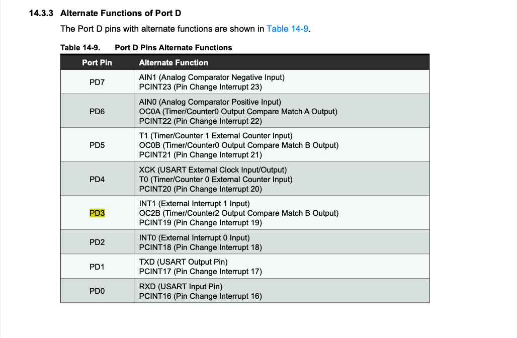
14.3.3 Alternate Functions of Port D page 97
Notice that 3 pins on Port D, 3, 5, and 6 all refer to a "(Timer/Counter2 Output Compare Match [A or B] Output)" and in PD3, the register is called OC2B.
We do a search on OC2B and on page 98, we find: “OC2B, Output Compare Match output: The PD3 pin can serve as an external output for the Timer/Counter0 Compare Match B. The PD3 pin has to be configured as an output (DDD3 set (one)) to serve this function. The OC2B pin is also the output pin for the PWM mode timer function.” That last sentence has caught our eye!
And on the same page, we also see a similar entry for pins 5 and 6. And when we do a search on a Port B pin such as Arduino pin 11 or PB3, we can find the similar information (similar table, page 91) such that we are able to create the following table:
| Arduino | ATmega328 | Register | Timer/Counter | # of bits |
|---|---|---|---|---|
| 3 | PD3 | OC2B | 2 | 8 |
| 5 | PD5 | OC0B | 0 | 8 |
| 6 | PD6 | OC0A | 0 | 8 |
| 9 | PB1 | OC1A | 1 | 16 |
| 10 | PB2 | OC1B | 1 | 16 |
| 11 | PB3 | OC2A | 2 | 8 |
This is where we start. We don’t “assign” a pin to a PWM, as they are already assigned, as in PD3 is connected to OC2B and PB1 is assigned to OC1A. Now we need to determine what needs to happen to make a PWM output appear on that specific pin/register combination. This table is important to understand as we will continue to build it out to help us document the PWM functionality and control of the Atmega328 chip. This table will help us to program PWM mode by consolidating the information into one location.
Starting from left to right:
- Arduino pin number
- Corresponding ATmega328 pin number
- Timer/Counter Compare Register which is the “output pin for the PWM mode”
- The number of the Timer/Counter (0-2) to which the pin is assigned
- The number of bits in the Timer/Counter (8 or 16)
The third bullet will be the most important one from a configuration perspective. The data is organized by Timer/Counter, Chapter 15 covers Timer/Counter 0, Chapter 16 covers Timer/Counter 1 and Chapter 18 covers Timer/Counter 2.
Let me emphasize this as a comparison to analogWrite. In analogWrite, the function asks for two parameters, a pin and a value. The pin will be one of the six that can deliver a PWM signal and the value is a number to be divided by 255 to determine the duty cycle. Therefore, analogWrite(3, 127) would deliver a 490Hz signal with 127/255 ~ 50% duty cycle on Arduino pin 3, ATmega328 pin PD3.
In reality AND in our efforts, the pins are tied to Timer/Counters and we need to program a specific Timer/Counter to achieve PWM on a specific pin. We are going to use the table above to accomplish this. While admittedly more complex and mildly inefficient from a programming perspective, this approach will be incredibly efficient (5x) from a code execution perspective. Let’s start the effort by setting aside “which pin”, and simply start with the first timer/counter section in the datasheet, 15. 8-bit Timer/Counter0 with PWM.
PWM in Chapter 15#
A datasheet can be overwhelming, in fact, it always is, at first. I approach one by scanning for what I need and ignoring most of everything else. In this case, we’re looking for PWM, so we scan for “PWM” in Chapter 15. We see it in the Overview bullet points. We see it referenced in 15.2.2 Registers. And then we see it, 15.7.3 Fast PWM Mode. Even the first sentence sounds exactly like what we want “The fast Pulse Width Modulation or fast PWM mode (WGM02:0 = 3 or 7) provides a high frequency PWM waveform generation option.” Great!
It continues on to say “The fast PWM differs from the other PWM option by its single-slope operation. The counter counts from BOTTOM to TOP then restarts from BOTTOM” It sounds fairly simple. Now what?
Configuring a Microcontroller#
This is where it becomes a little bit complicated. It took me a while, to determine how to explain setting up a timer. First, its important to understand that all aspects of a microcontroller are controlled by registers. This is a fundamental aspect of programming a microcontroller. You set bits in registers and the microcontroller will execute a task in a very specific manner. Therefore, to program a function on a microcontroller, such as PWM, you need to:
- Identify the registers that control the function (in this case, PWM)
- Understand the role each bit in the register serves in affecting that function
- Be methodical as to how you approach setting the bits in the registers
Configuring Timer/Counter 0 for Fast PWM#
1. Identify the registers#
This isn’t easy with the ATmega328P. The registers aren’t specifically identified as “use these registers to configure the timer”. Fortunately, we can skim and search and find on page 104, the following information “The counting sequence is determined by the setting of the WGM01 and WGM00 bits located in the Timer/Counter Control Register (TCCR0A) and the WGM02 bit located in the Timer/Counter Control Register B (TCCR0B).”
And if we continue to read/skim/search, we’ll get to page 113 “15.9.1 TCCR0A – Timer/Counter Control Register A” and then we will begin to understand how to setup our timer. It’s important to capture the information as soon as you find it, so let’s update the table from above to indicate the registers:
| Arduino | ATmega328 | Register | Timer | # bits | Control Registers |
|---|---|---|---|---|---|
| 3 | PD3 | OC2B | 2 | 8 | TCCR2A/TCCR2B |
| 5 | PD5 | OC0B | 0 | 8 | TCCR0A/TCCR0B |
| 6 | PD6 | OC0A | 0 | 8 | TCCR0A/TCCR0B |
| 9 | PB1 | OC1A | 1 | 16 | TCCR1A/TCCR1B |
| 10 | PB2 | OC1B | 1 | 16 | TCCR1A/TCCR1B |
| 11 | PB3 | OC2A | 2 | 8 | TCCR2A/TCCR2B |
2. Understand the role of each bit#
If we start on page 113 “15.9.1 TCCR0A – Timer/Counter Control Register A”, with the leftmost bits, we see that the OC0A pin is controlled by bits 6-7. And if we look at our table, OC0A corresponds to PD6. (And OC0B, bits 4-5, correspond to PD5).
We also see the lower 2 bits of the 3 bit, control called WGM, Waveform Generation Mode. We’ll cover this set of bits in a moment.
Let’s quickly take a look at the next section, 15.9.2 TCCR0B – Timer/Counter Control Register B. It has two bits 6-7, which aren’t active when we are NOT doing PWM. So we can ignore them. The next two bits don’t matter, then we get to our third bit of WGM.
So WGM, sets the waveform desired. We know we want Fast PWM, so we only have two choices, Mode 3 (bits 011) or Mode 7 (bits 111). Let’s keep it simple and use Mode 3.
The last three bits are a scalar for the clock, the scalar determines the initial frequency of the PWM. The best way to understand it is to follow the formula on page 109, where it states: “The PWM frequency for the output can be calculated by the following equation:” freq = f(clkIO)/(N * 256). We can use our own numbers and see if it makes sense.
- f(clkIO) = 16Mhz so 16 x 10^6 / (256 * 64) = 976.56Hz
- ~= 980Hz from Arduino.cc documentation (pins 5 and 6: 980 Hz)
We’ve got a rough idea as to how to set the bits in the registers. It helps to begin to map out what you want to do to close specifically as to how to set the bits.
3. Be Methodical in Setting the Bits#
At this point, you want to begin to create code to set the bits. The best way to start is to simply write documentation to support what you want to accomplish. And to help you tie the documentation to the code, add it as comments in the file.
Here is what we believe we want:
- Fast PWM mode, set WGM2:0 to 011 (see p115)
- Non-inverting mode for PD5 or OCR0A, set COM0A1:0 to 10 (page 113)
- Inverting mode for PD6 or OCR0B, set COM0A1:0 to 11 (page 113)
- Divide the clock by 64, set CS02:0 to 011 (page 117)
Now let’s put it into code:
/* fastPWM: setup 8-bit Fast PWM using Timer/Counter 0

Timer 0 Configuration, 8bit Fast PWM p113-7
TCCR0A - Timer/Counter0 Control Register
[ COM0A1 COM0A0 COM0B1 COM0B0 0 0 WGM01 WGM00 ]

TCCR0B - Timer/Counter0 Control Register
[ FOC0A FOC0B 0 0 WGM02 CS02 CS01 CS20 ]

COM0A1:0 = 10 => Clear OC0A on compare match (non-inverting)
COM0B1:0 = 11 => Set OC0B on compare match (inverting)
WGM02:0 = 011 => Fast PWM, Update at Bottom, TOV=MAX
CS02:0 = 101 = clkio / 011 scalar 011 => 1/64

PWM Pins p97
ARD5 PD5 OC2B 8bit Timer/Counter 0 OCR0B
ARD6 PD6 OC2A 8bit Timer/Counter 0 OCR0A

Specific to parameters below
Frequency: 16MHz / 256 / 64 = 976.56Hz
Pin 5/PD5/OCR0B has a 50% duty cycle or 127/255
Pin 6/PD6/OCR0A has a 25% duty cycle or 63/255
*/
#include <avr/io.h>

int main (void)
{
    // reset both timer/counters
    TCCR0A = 0;
    TCCR0B = 0;
    // set UNO pin 5/PD5 and pin 6/PD6 to output
    DDRD |= _BV(DDD5);
    DDRD |= _BV(DDD6);

    // TCCR0A [ COM0A1 COM0A0 COM0B1 COM0B0 0 0 WGM01 WGM00 ] = 0b10110011
    TCCR0A = _BV(COM0A1) | _BV(COM0B1) | _BV(COM0B0) | _BV(WGM01) | _BV(WGM00);
    // TCCR0B [ FOC2A FOC2B 0 0 WGM02 CS02 CS01 CS00 ] = 0b00000011
    TCCR0B = _BV(CS01) | _BV(CS00);
    OCR0A = 63;
    OCR0B = 127;
}
I used the Labrador to examine the waveform created by the fastPWM code.
- Yellow signal is CH1/PD5 output and shows a 50% duty cycle at 974Hz
- Blue signal is CH2/PD6 and shows a 25% duty cycle, inverted wave also at 974Hz
It worked!
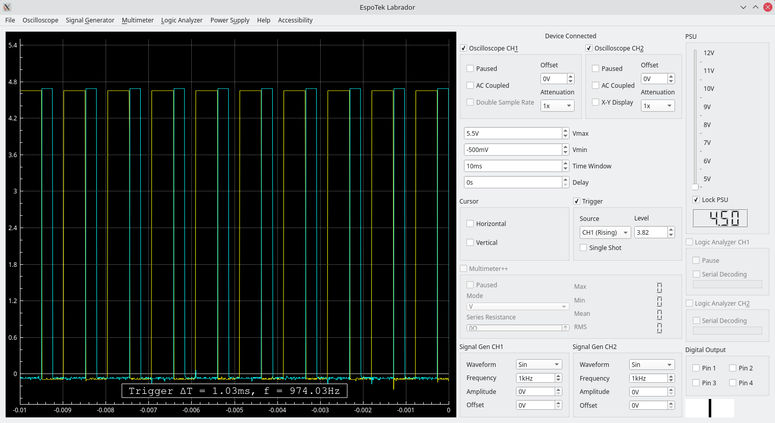
Waveform created by fastPWM code above